Updated 21 September 2022 by Michael Gordon
The Keysight DSOX 1202G oscilloscope with built-in signal generator can produce BODE plots which are similar to the function of a VNA (Vector Network Analyzer).
Standing Wave Ratio When you send 100 watts to an antenna, what is wanted is for every one of those watts to fly off into space. For a variety of reasons, some of it bounces back into the radio, and the proportion that bounces back, compared to what is sent to the antenna, is called Standing Wave Ratio. A perfect score is shown as 1:1 (One-to-one) which means nothing comes back; every watt sent does not come back.
BEWARE: It might also not be radiating into space! A dummy load or 50 ohm resistor shows a perfect 1:1 standing wave ratio, meaning there aren't any "standing waves" at all.
It is called standing wave because the waves returning cross the waves going, and at certain locations along the coax these waves null each other and at other locations these waves add together for twice the voltage and if that happens to be at the final amplifier transistors, well, it could destroy them if you are transmitting full power into an open circuit (antenna became disconnected somehow).
Update: That's how it seems to work but really it just compares forward current and voltage and in a type of bridge turns forward current into a voltage which then subtracts from forward voltage and so long as the destination is 50 ohms resistive, this cancellation is complete and "reflected" is zero for perfect SWR. If the destination isn't 50 ohms, the cancellation is incomplete (or excessive) and the residual shows up on the SWR meter. But it will also show up if there's reactive element, capacitive or inductive because phase cancellation won't take place (completely or in part).
An SWR meter shows you the magnitude of mismatch but gives no hint what to do about it. An oscilloscope can show not only magnitude, but phase of the reflection, and from that you can decide what to do. But remember, it isn't actually showing you the reflection; but rather the effect OF the reflection on the point of measurement.
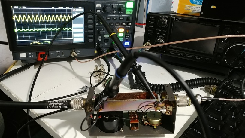
A simple analysis can even use your radio transmitter as the "exciter" but of course turn down the power. I use the signal generator inside the Keysight oscilloscope, set at 1 volt peak-to-peak so that's 0.35 volts RMS on 50 ohms, or 7 milliwatts.
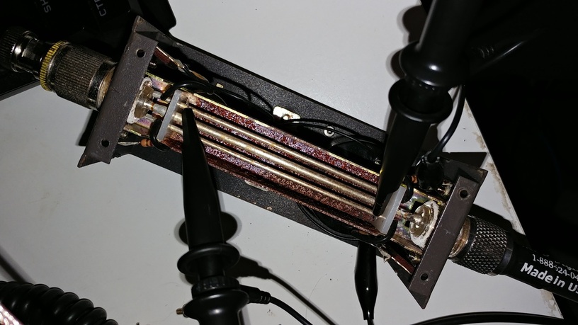
I clip the oscilloscope probes to each sense rod, opposite of the 50 ohm resistor soldered to only one end of each sense rod.
The analysis then consists of sweeping the frequencies and plotting the amplitude and phase of the reflection compared to the forward power. The Keysignt oscilloscope automates this process but it can be done manually with a signal generator and oscilloscope. That is basically how the MFJ antenna analyzer works; you manually sweep the frequency and observe the resistive and reactive values.
Please forgive the corrosion on this vintage Lafayette SWR meter. It spent about 12 years in Hawaii's salty corrosive air.
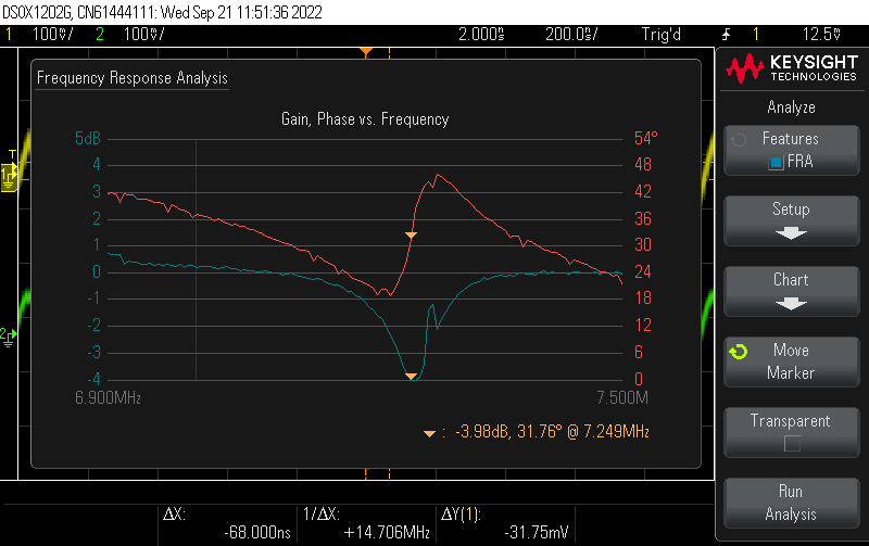
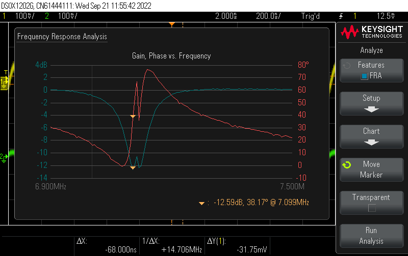
Here is when the main loop is mostly tuned but the matching capacitor is nowhere near correct, turned too far clockwise. The dip seems okay but is only 4 db (corresponds to SWR of 4.4). Tuning the main capactor you will see the dip but that's not all you need to do with this kind of tuner.
If viewed as a dual trace oscilloscope you would see signal on both probes but you would not be able to eliminate the reflection.
We adjust the matching capacitor for lowest SWR or dip in reflection. It doesn't quite reach zero but it's pretty good. Tuning one de-tunes the other so it is useful to go back and forth becoming perfect or at least good enough.

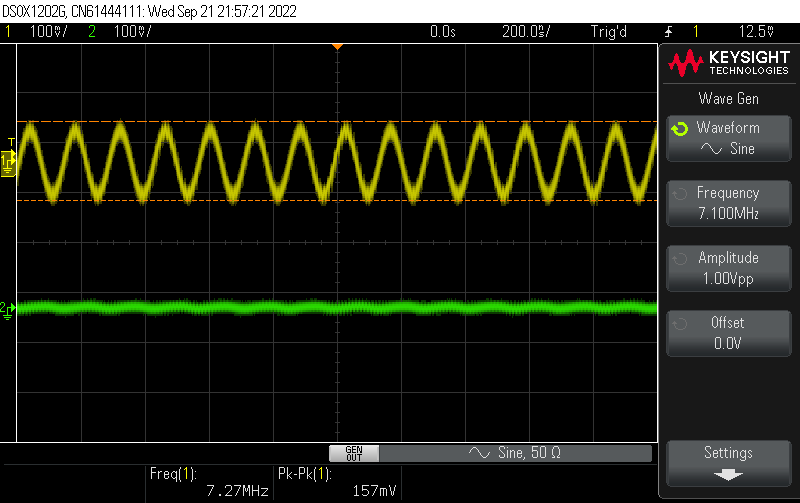
Here we are approaching perfect, just a wee bit too much on the matching capacitor knob. This produces two SWR dips.
Looking at the signal from the oscilloscope probes, it is easy to see the reflected signal on the bottom and also the phase of the reflection. In this example, the phase is neither completely in phase nor out of phase, meaning that the antenna is almost tuned but there's a reactive component to it. Tiny adjustments of the matching capacitor might eliminate that residual reactance.
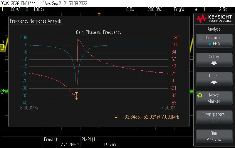
It only takes about three adjustments of the matching capactor and main loop tuning capacitor to achieve perfection. Notice that the cursor is positioned at 7.099 MHz, the loop is tuned for 7.100 MHz, so we are 1 KHz low. We have -33.84 db down which means almost zero reflection (there's a chart somewhere to convert from DB to SWR) and it appears a zero phase angle right at 7.100 MHz.
It should be apparent that a properly tuned, High-Q loop is extremely sharp or narrow in bandwidth. This is an inconvenience of course but also eliminates nearby interfering frequencies. It looks like about 30 db down only 100 KHz away from the desired frequency.
Let's zoom in on the spectrum and fine tune the tuner with the scope. The radio itself just shows perfect SWR BUT at a slightly different frequency (7.128 MHz) signifying that the test setup itself alters the tuning of the loop and so will the radio.
How good does it get?
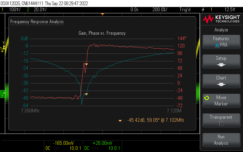
How about 52.82 db deep notch at 7.101 MHz and essentially zero phase shift (non-reactive). Using
the Return Loss to VSWR Ratio Chart the
VSWR is about 1 to 1.004
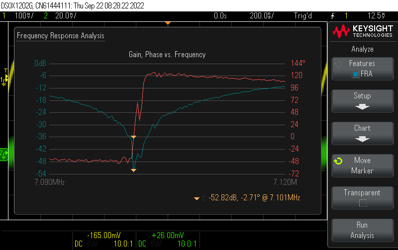
What's the bandwidth? Well, at 7.102 MHz (one kilohertz higher) we start climbing out. The notch itself seems to be 500 Hz or less, incredibly sharp. The useful bandwidth is about 10 kHz.
It has been a mystery for some years how these things work and the usual explanation involves enough math that my eyes glaze over (MEGO).
The secret is actually very simple; but difficult to explain. It takes advantage of capacitance and induction and has nothing to do with actual direction! When a transmission line is perfectly matched, a voltage at the point of measurement exists and also a current and they are in phase. What you do is simply subtract the voltage created by the current (by induction), from the voltage that is already voltage (by capacitance in the case of the Lafayette SWR meter), and when everything is perfect this subtraction results in zero. If the antenna impedance is too low, current will be high and voltage low, and this cancellation does not take place, there will be a residual voltage and it will be out of phase.
In case antenna impedance is too high, voltage will be high and current low; cancellation won't be complete and the sense rod will have a voltage and it will be in phase.
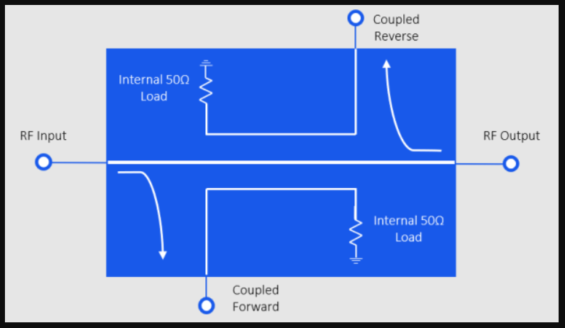
The Lafayette SWR meter is a type of directional coupler that uses a combination of capacitance for voltage measuring and inductance for current measuring. The capacitance is from the center conductor to each of the sensing rods nearby. Induction is also from the center conductor to the sensing rods.
What is important is that capacitance charges the rod along its entire length with the same voltage proportional to the voltage on the center conductor.
However, the inductance has polarity, one end of the rod will go positive and the other end will go negative because of the induced current in the rod.
With careful spacing and resistors, the induction and capacitance are made to match a 50 ohm transmission line; and when the voltage and current are just right, the capacitive charge on the rod will be exactly canceled by the iduction charge on the rod at one end of the rod, but added together at the other end. So we CALL one end the forward end and the other end is the reverse end; but we use two rods since you need that 50 ohm resistor to develop a voltage from the induction.
The SWR meter simply reports mismatch.
An oscilloscope can reveal whether the mismatch is in phase (antenna impedance too high) or out-of-phase (antenna impedance too low).
If the resistance is correct but there's a reactive component in the antenna, the phase will be neither in or out; but some phase angle between 0 and 180. the SWR meter will still show that it isn't a perfect match but it cannot show you what is wrong. An oscilloscope (or real antenna analyzer or VNA) can reveal by the phase difference what is wrong and needs to be done. too-short antennas tend to be capacitive (if I remember right) and will show up as REV voltage lagging forward current, a too-long antenna will show up as inductive in which case REV voltage will lead forward current.