Similar plots can be made with some versions of NanoVNA:
Youtube video using NanoVNA to evaluate a crystal.
Quartz crystals were used from the 1920's through about 1970 for amateur radio frequency control. Novice licensees were required to use a crystal controlled transmitter. You could listen on any frequency but of course you could only transmit on a frequency for which you have a crystal. Having a VFO (variable frequency oscillator) was a big deal. Modern radios still use a crystal oscillator as a reference to stabilize the VFO.
Crystals have a unique property of having two resonant frequencies; one that is a series resonance like a series LC ciruit; the other is a parallel resonance like a trap or tank circuit and blocks that frequency. These typically are very close together as we shall see. Parallel designed crystals can be used in either series or parallel mode but series designed crystals can only be used in series oscillator circuits (or did I get that backwards?).
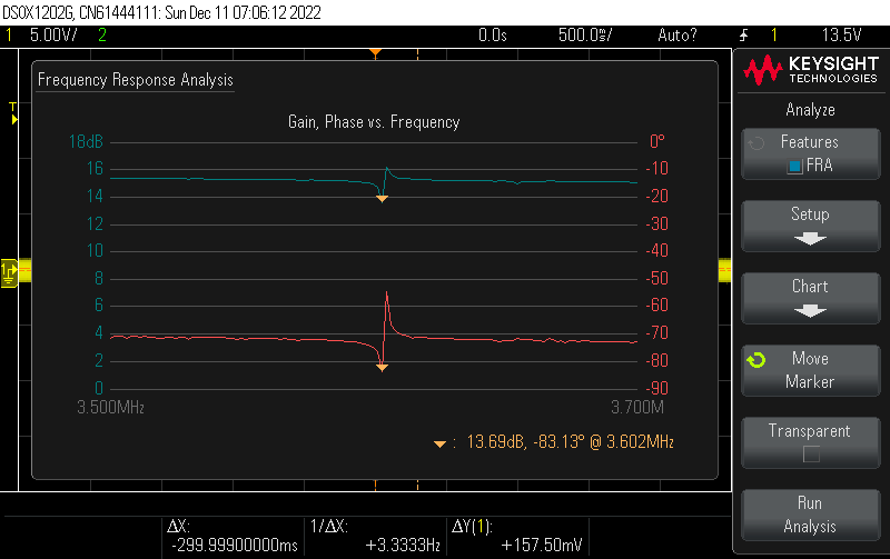
The first set of 3 screenshots is with the crystal shunting to ground. Channel 1 and channel 2 are joined to a high-impedance signal source and the crystal provides a path to ground. Scope channels 1 and 2 watch the signal source and the crystal will shunt to ground at its series resonant frequency and produce a peaking at its parallel resonant frequency.
200 KHz wide view of the crystal providing a path to ground creating a dip at its series resonance and a peak at its parallel resonance. Yellow is signal strength and magenta is phase.
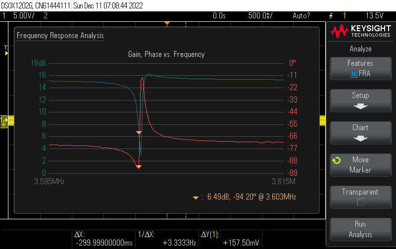
20 Kilohertz span, series (dip) frequency.
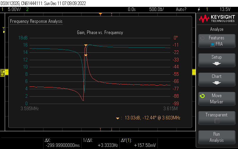
20 Kilohertz span, parallel frequency.
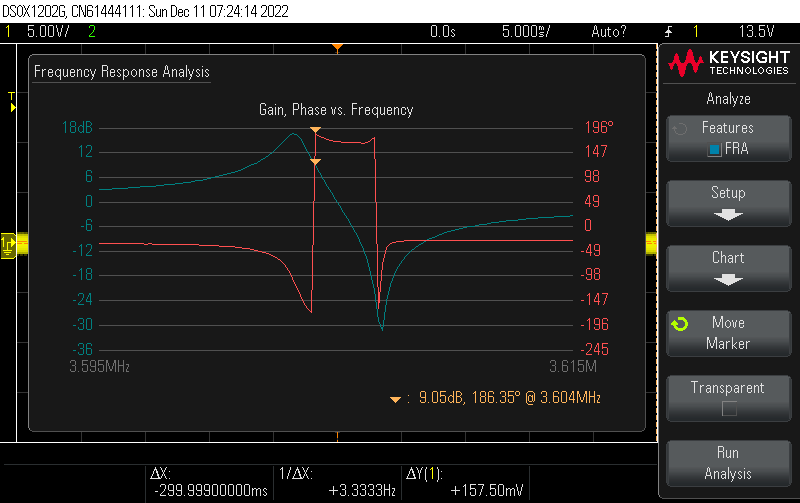
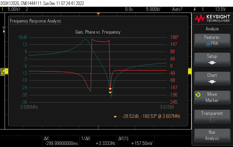
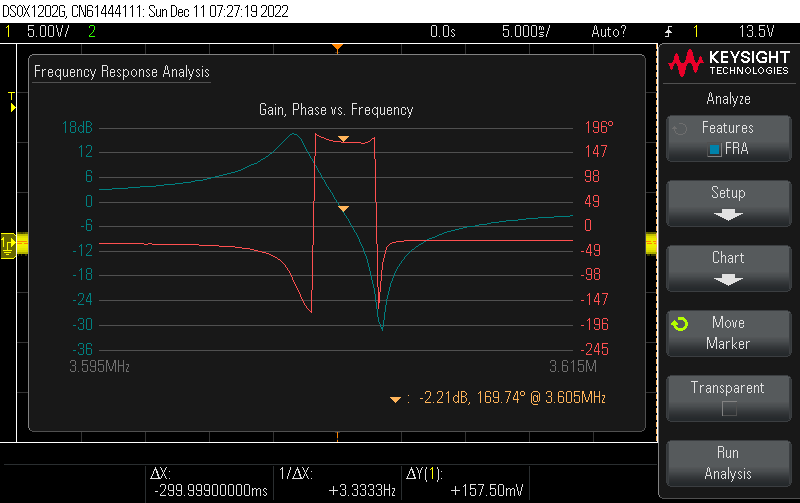
The second set of 3 screenshots is with the crystal in series between signal source and oscilloscope input. Signal source remains set to high impedance although in series it shouldn't matter much.
In this scenario, the series resonance will produce a signal strength peak (rather than a dip) and the parallel resonance will block the signal and produce a pronounced dip. Unexpectedly, the response is nearly flat for nearly 2 KHz making a nice shaped bandpass filter. Through this bandpass the phase changes on a nearly linear manner.
These three screenshots are the same but I have placed the cursor at the start, end and middle of the bandpass. Since the phase change is zero in the middle, that is where the crystal oscillator will tend to operate.
On startup, the amplifying device (tube, transistor or FET) will send a small noise to the crystal and a narrow spectrum of noise will get through. Preferentially, the signal at the center of the passband will be amplified and fed back to the crystal, rapidly growing until the amplifier saturates. But it is a band of signals, not just a single frequence. This spectrum noise is called "phase noise" and is relatively ungood particularly for things like FM radio and digital modes. Reducing the gain of the amplifier so that only the center of the passband obtains enough gain for feedback reduces or eliminates phase noise.
Silicon Labs 5351a Clock Generator chip used in NanoVNA. Two PLL's are set to various multiples of a 25 MHz crystal and then mixed together to produce a nearly continuous range of output frequencies.
MultiSynth White Paper with details on how the chip in a NanoVNA produces the frequencies it needs.
The Si5338’s low phase noise, high-frequency VCO supplies a high-frequency output clock to the MultiSynth block on each of the four independent output paths. The first stage of the MultiSynth architecture is a fractional-N divider, which switches seamlessly between the two closest integer divider values to produce the exact output clock frequency with 0 ppm error. To eliminate phase error generated by this process, the MultiSynth calculates the relative phase difference between the clock produced by the fractional-N divider and the desired output clock and dynamically adjusts the phase to match the ideal clock waveform. This novel approach makes it possible to generate any output clock frequency without sacrificing jitter performance. Based on this architecture, each output clock can be individually programmed to generate any frequency from 0.16 to 350 MHz, and select frequencies to 700 MHz. Typical jitter performance enabled by this MultiSynth-based architecture is 1 ps RMS.
By Roger Harrison, VKZZTB, 14 Rosebery Street, Balmain NSW 2041, Australia
Ham Radio March 1976 See page 10 for detailed article on crystal
https://worldradiohistory.com/Archive-DX/Ham%20Radio/70s/Ham-Radio-197603.pdf Same file but "out there". oscillators.