Commentary by Michael Gordon AG7MG
To suppress EMI (electromotive interference) or RFI (radio frequency interference) I decided to insert a ferrite common mode choke in a DC power supply line.
A handy source of small ferrite cores or "beads" is to salvage them out of abandoned cables such as VGA cables that were once in common use but now almost entirely abandoned. It is a challenge to get the cores out but that is a different story.
the more turns you make the better but I had room for only one turn.
Is it effective? Obviously it depends on frequency. It blocks VHF pretty well but was ineffective for the 1 MHz interfering signal. Here is how I measured it.
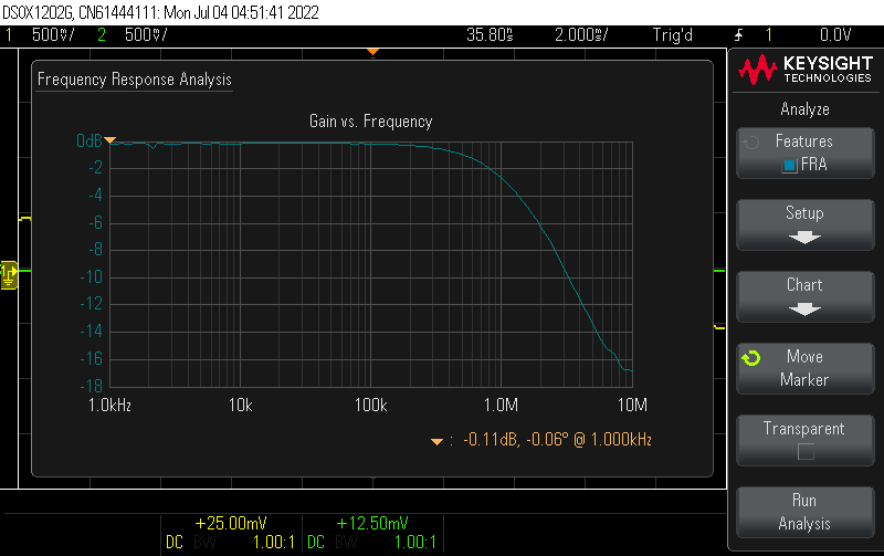
The Keysight oscilloscope has a Bode Plot capability, phase and gain versus frequency up to about 20 megahertz. This is similar in function to a VNA (NanoVNA) which can be used for similar purpose and much higher frequency where the oscilloscope is suitable for much lower frequency uses (with some overlap).
This can be used to determine the inductance.
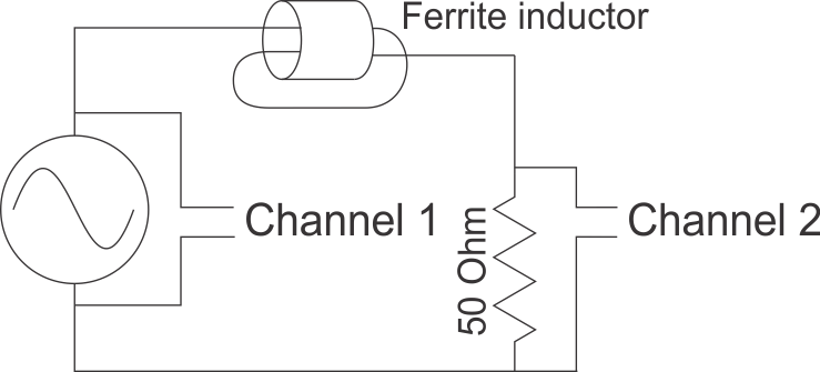
Channel 1 gets the source from the generator, full strength.
Channel 2 is after the choke and in parallel with a 50 ohm termination resistor.
Effectively, this puts the choke in series with 50 ohms and at a certain frequency, the impedance of the choke will be 50 ohms, matching the 50 ohm terminater, producing exactly a 50 percent drop in voltage as seen across the termination resistor and that is what is being measured on Channel 2. This is 1/4 power so will be the 6 db point in the Bode plot. Observe the frequency at which this takes place. In this demonstration, 6 db down happens at 2 megahertz.
Since XL=2 pi F L, we swap things around a bit, divide both sides by (2 pi F) and you get L = XL/(2 pi F) or in this case L = 50/(2 pi 2000000).
Comes out to 3.9 microhenries.